Passive Intermodulation (PIM) Tech Note
Passive Intermodulation (PIM) is an interference phenomenon attributable to the many sources of non-linearity within a communication system. In high-power, multichannel systems, these nonlinear sources generate higher order harmonics of the fundamental frequency. The fundamental signal and the harmonic products then mix together to generate a predictable set of new frequencies. The result is that certain parts of the frequency spectrum become unusable for the receive portion of the communication system. While careful allocation of receive and transmit frequencies can help to avoid this problem, spectrum crowding and assigned frequency allocation may make this impossible.
If you determine that your system may be affected by PIM distortion, there are a few basic guidelines you can use to minimize PIM generation. The following sections describe in more detail the generation of PIM products and different material constructions as they pertain to coaxial cable systems.
Background
One of the major sources of PIM in a coaxial cable assembly comes from the contact resistance of metals within the cable and connector surfaces. These surfaces behave like diodes that cause a nonlinear current voltage trace. These nonlinearities generate harmonic frequencies that can be represented as:
One of the major sources of PIM in a coaxial cable assembly comes from the contact resistance of metals within the cable and connector surfaces. These surfaces behave like diodes that cause a nonlinear current voltage trace. These nonlinearities generate harmonic frequencies that can be represented as:
Fn(wt) = A0 + A1cos(wt + ø1) + A2(cos2wt + ø2) +...
<->Fn = Fn ± 2Fn ± 3Fn...
In a system with two or more transmission frequencies, these harmonics can mix together to form multiple frequencies. For example, in a two-tone system, with carriers at F1 and F2, the output spectrum could equal:
Fout = F1 + F2 + 2F2-F1 +2F1 -F2 +3F2-2F1 +3F1-2F2...
In general, these mixing products can be referred to by their order, so that:
Fn=1st order
2F2-F1 =3rd order
3F2-2F1=5th order...etc.
Fortunately, the power content of the higher order harmonics (i.e., beyond the fifth harmonic) drops dramatically. Also, your system may employ either filters or other devices that further reduce higher order harmonics. Nevertheless, the potential still exists for a significant power content in the third through ninth order equations. If these frequencies fall within your receive path, your system's noise figure will degrade.
Options
After determining that your system may be affected by PIM, you have several cable options that may reduce or eliminate your problem. Several papers discuss PIM (see references below) and the use of various contact materials. Since each surface and metal-to-metal contact point within the coaxial RF field may generate PIM products, you should focus on those areas. The problematic surfaces fall into three major categories: cable, cable-to-connector junction, and connector-to-connector junction.
Cable
The cable itself is probably the easiest factor to control. In general, a solid center conductor reduces the number of point contacts versus a stranded center conductor. However, studies show that, by using metals with low contact resistance such as silver or gold, the problem can be virtually eliminated.
The second source of PIM is surface oxides on either the inner or outer conductor. These semiconducting oxides are one of the greatest factors in the generation of PIM. Thus, two very common center-conductor materials, aluminum and copper, should not be used without an overplate of non-oxidizing metal.
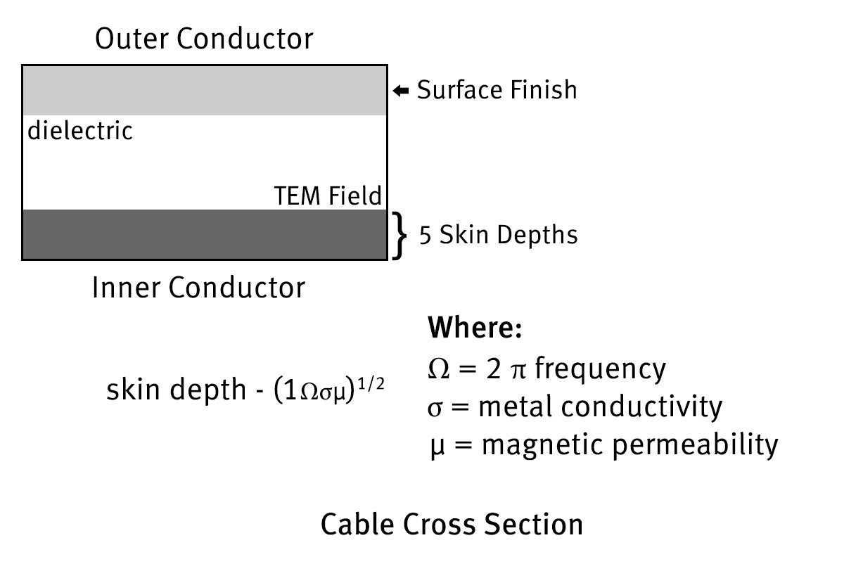
Finally, conductor surface finishes should either prevent the formation of oxides at the metal-to-finish junction, or be sufficiently deep that they extend at least five "skin depths" normal to the TEM field. This is illustrated in the figure.

Cable-to-connector termination
The single most important concern is the degree of contact between the cable and connector. Since a partial contact results in a nonlinear device, ensure that you have 360-degree solder attachment of the connector to the cable. Take care to prevent excess solder from extending beyond the connector-to-cable joint.
Connector
Standard connector interfaces contain many mating surfaces that can generate PIM. In general, you should eliminate along the signal path all metals that exhibit magnetic or paramagnetic properties or have surface oxides.
References
- M. Bayrak, M. Eng and F. A. Benson, 'Intermodulation Products from Nonlinearities in Transmission Lines and Connectors at Microwave Frequencies,' Proc. IEEE, Vol. 122, No. 4, April 1975.
- M. Bani Amin and F. A. Benson, 'Coaxial Cables as Sources of Intermodulation Interference at Microwave Frequencies,' IEEE Trans. ed., Vol. EMC-20, No. 3, August 1978, pp 376-384.
- F. Arazm and F. A. Benson, 'Nonlinearities in Metal Contacts at Microwave Frequencies,' IEEE Trans. ed., Vol. EMC-22, No. 3, August 1980, pp 142-149.
FOR INDUSTRIAL USE ONLY
Not for use in food, drug, cosmetic or medical device manufacturing, processing, or packaging operations.