Part Number Information: GORE® Microwave / RF Assemblies
Part Number
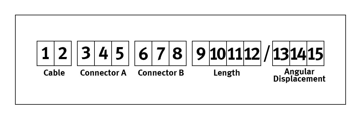
Gore part numbers consist of a minimum of 12 and a maximum of 15 alphanumeric characters. Groupings of these characters have a specific meaning, as illustrated below. Characters 1 and 2 define the cable type.
Characters 3, 4, and 5 define the connector (“A”) to be used on one end of the assembly. Characters 6, 7, and 8 define the connector (“B”) to be used on the second end of the assembly.
Characters 9, 10, and 11 define the assembly length in inches. Lengths which require only one or two digits (6 or 24 in., for example) should be preceded by zeroes in the unused positions (006, 024). Character 12 is used to further define lengths which are not in whole-inch increments (24.5 in., for example). Do not use a two place decimal: round to the most desirable tenth of an inch for your application. If your length is a whole-inch increment, a "0" should be placed in position 12.
Characters 13, 14, and 15, preceded by a slash are used only when an assembly has two angled or “D” mount connectors (or a combination thereof) to specify angular displacement. Angles less than 100° should be preceded by a zero in box 13. If characters 13, 14, and 15 are not specified, the assembly will be supplied with an angular displacement of zero degrees. Characters 13, 14, and 15 are required for ordering purposes only, and are not stamped on the assembly I.D. tube unless specified. To specify angular displacement in the Assembly Builder provide the information in the “Comments” field on “Other Requirements” page.

Specifying Angular Displacement
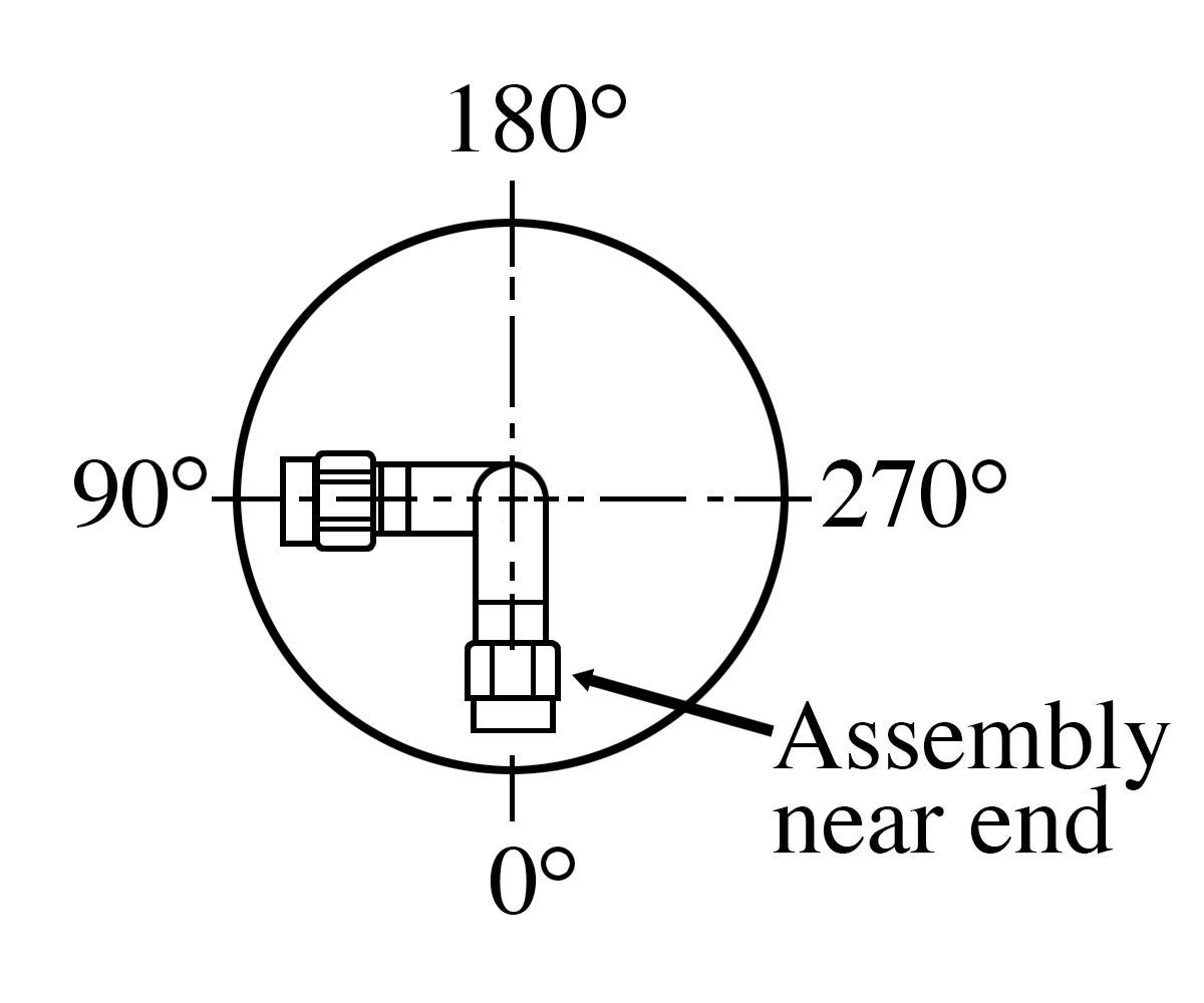
Angular displacement of the two connectors must be specified to avoid the application of excessive torque to the assembly during installation. The shorter the assembly, the more important the correct specification becomes. Angular displacement should be specified per the drawing above.
Position the assembly so that the near-end (end A) right angle connector (or “D” mount flat) faces downward (0° position per drawing). Sight along the assembly to determine the angular displacement of the far end (end B) right angle connector (or “D” mount flat), as compared to the near-end connector. The standard manufacturing tolerance on a specified angular displacement is ± 10° for assembly lengths to 24 in. (609.6mm), and ± 20° for lengths longer than 24 in. (609.6mm). If relative angular displacement is not specified, we will assume that a zero degree displacement (connectors and connector flats in the same plane) is desired.

FOR INDUSTRIAL USE ONLY
Not for use in food, drug, cosmetic or medical device manufacturing, processing, or packaging operations.