Raised Face or Flat Face Flanges
- Follow steps A through D of the General Installation Procedure (listed above) to install the gasket tape.
- The adhesive strip allows for overhead gasket installation.
- When closing the flange ensure the gasket tape remains in position.
On the Tongue
- Follow steps A through D of the General Installation Procedure (listed above) to install the gasket tape.
- The adhesive strip allows for overhead gasket installation.
- When closing the flange ensure the gasket tape remains in position.
In the Groove
- Follow steps A through C of the General Installation Procedure (listed above) to prepare and begin laying the gasket tape within the groove.
- To complete the gasket described in step D, lay the last 30 cm (1 ft) of the gasket tape in the groove, and mark the location of the starting skive cut using a ball point pen.
- Perform the closing skive cut on a flat surface.
- Complete the gasket by removing the rest of the adhesive backing, laying the gasket in the groove, and overlapping the skived cuts.
- Follow steps A through D of the General Installation Procedure (listed above) to install the gasket tape.
- The adhesive strip allows for vertical gasket installation.
- When closing the flange ensure the gasket tape remains in position.
- Follow steps A through C of the General Installation Procedure (listed above) to prepare and begin laying the gasket tape within the groove.
- To complete the gasket described in step D below, lay the last 30 cm (1 ft) of the gasket tape in the groove, and mark the location of the starting skive cut using a ball point pen.
- Perform the closing skive cut on a flat surface.
- Complete the gasket by removing the rest of the adhesive backing, laying the gasket in the groove, and overlapping the skived cuts.
- Prepare the Flange. Completely clean the surface to ensure optimal adhesion. Remove all oil, graphite, and other residue.
- Measure and cut the gasket tape so the length is slightly oversized by 3 mm (1/8"). Perform a 90° butt cut at both ends.
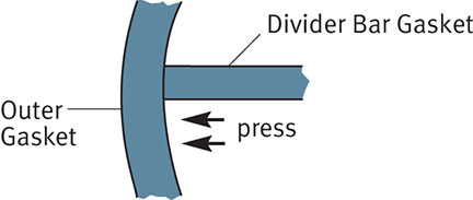
- Apply divider bar gasket
- Remove the adhesive backing and firmly press the end of the gasket into the outer gasket. Lay the tape across the divider bar and firmly press the other end into the outer gasket.
ATTENTION: Divider bars in Heat Exchangers rarely operate at significant differential pressures, therefore, a butt cut pressed firmly into the outer flange gasket will provide an adequate and successful seal. Gore does not recommend any alternative cutting techniques or overlapping at the divider bar and circular gasket interface.
- Follow steps A through C of the General Installation Procedure (listed above) to prepare and begin laying the gasket tape.
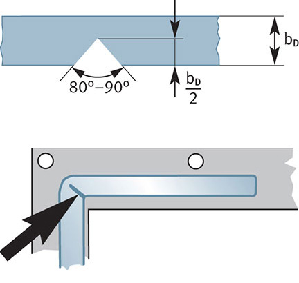
- Turn sharp corners.
- In order to ensure uniform stress to seal, GORE® Gasket Tape Series 500 should be notched at sharp corners.
- When approaching a sharp corner, cut away an 80–90° notch from the inner edge of the tape as shown.
- Bend the gasket around the corner. It is then held in place by the adhesive backing.
- Complete the gasket by following step D of the General Installation Procedure (listed above).