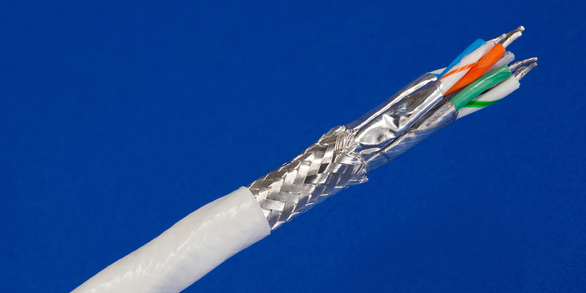
GORE Aerospace Ethernet Cables are engineered for the increasing data demands of modern airborne digital networks (Figure 1). They exceed Cat6a electrical requirements and deliver reliable signal integrity with sufficient margin for high-speed data transmission up to 10 gigabits over longer distances (Table 1). The unique design of these cables is 24 percent smaller and 25 percent lighter than standard Cat6a cables for greater flexibility and easier installation in challenging environments (Figures 2 and 3). Gore's engineered fluoropolymer materials enable this cable (26 AWG) to fit into a size 8 contact.
Typical Applications
- Avionics networks
- Cabin management systems
- Digital video systems
- Ethernet backbone
- Flight management systems
- In-flight entertainment (IFE) systems
Figure 1: GORE Aerospace Ethernet Cables
Standards Compliance
- ANSI/NEMA WC 27500 Performance Requirements: Environmental Testing, Jacket and Marking
- IEEE 802.3 1000BASE-T Gigabit Ethernet Cables: Ethernet Standard
- AS4373 Test Methods for Insulated Electric Wire
- FAR Part 25, Appendix F, Part I, BSS7230, and ABD0031 (AITM 2.0005): Flammability
- FAR Part 25, Appendix F, Part V, BSS7238, and ABD0031 (AITM 3.0008B): Smoke Density
- BSS7239 and ABD0031 (AITM 3.0005): Toxicity
Table 1a: Cable Properties (Electrical)
| Electrical Property | Value |
|---|---|
| Standard Impedance (ohms) | 100 ± 10 |
| Voltage Rating (V) | 500 |
| Velocity of Propagation (nominal) (%) | 80 |
| Time Delay (nominal) [ns/m (ns/ft)] - 24 AWG | 4.10 (1.25) |
| Capacitance [pF/m (pF/ft)] | 42.6 (13) |
| Dielectric Withstanding Voltage (Vrms) Conductor-to-Conductor Conductor-to-Shield |
1500 1000 |
Table 1b: Cable Properties (Mechanical / Environmental)
| Mechanical / Environmental Properties | Value |
|---|---|
| Jacket Material | Engineered Fluoropolymer |
| Jacket Color | White |
| Conductor | Silver-Plated Copper |
| Conductor Color-Coding | Solid Blue/White with Blue Stripe Solid Orange/White with Orange Stripe Solid Green/White with Green Stripe Solid Brown/White with Brown Stripe |
| Dielectric Material | ePTFE/PTFE |
| Dielectric Material | -55 to 200 |
Figure 3: High-Density Construction
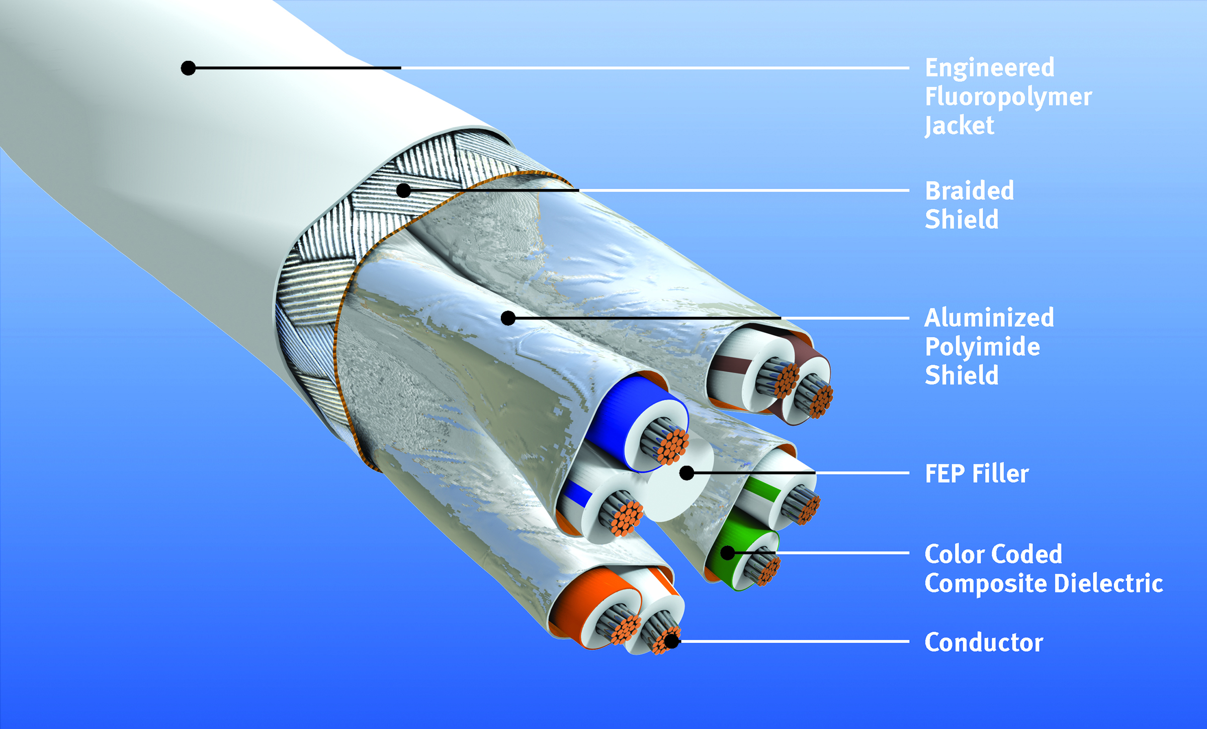
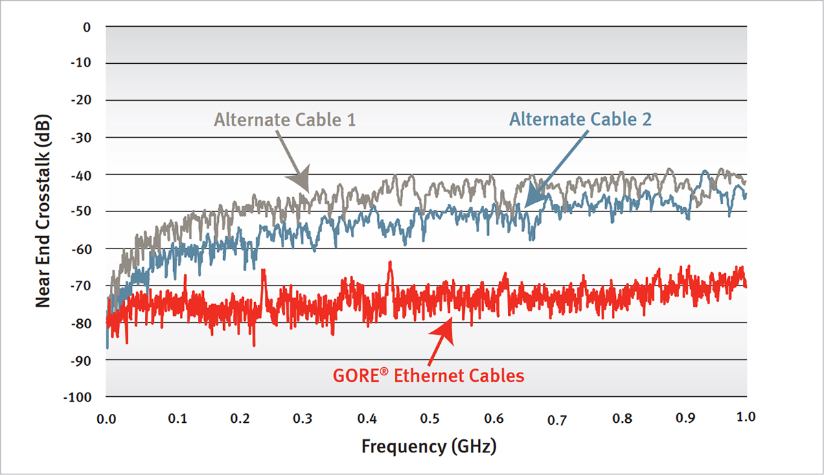
Figure 5: NEXT Comparison
Ordering Information
GORE Aerospace Ethernet Cables are available through several global distributors in a variety of standard sizes (Table 2). Visit gore.com/cable-distributors for the list of distributors. Gore also offers custom cables and terminated assemblies. For more information, please contact a Gore representative.
Figure 2: Smaller Cat6a Cable Diameter
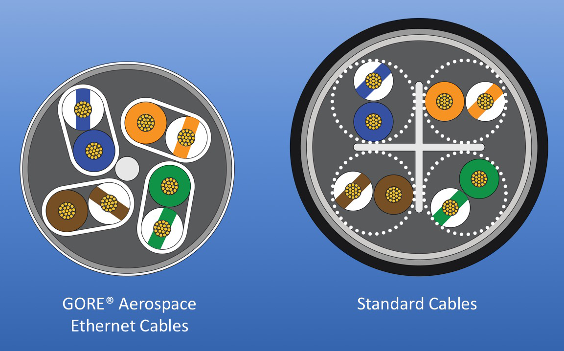
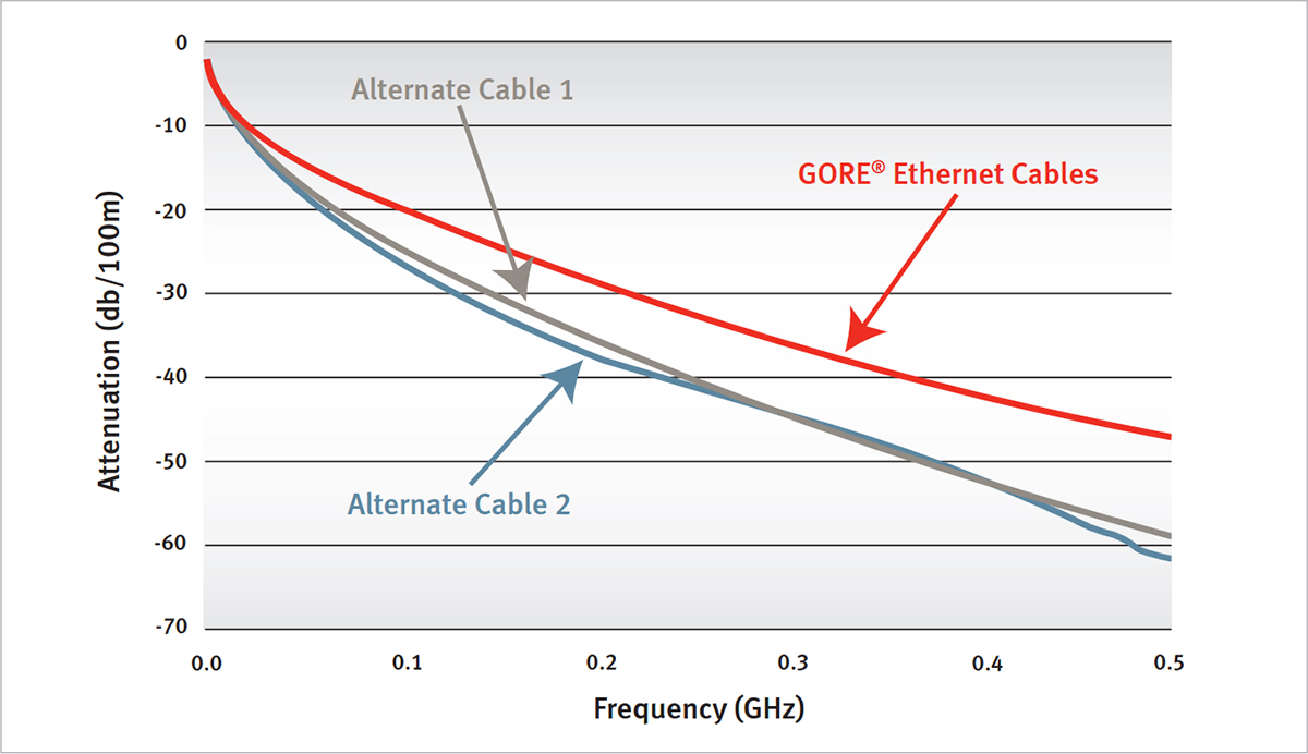
Figure 4: Attenuation Comparison
Reliable Signal Integrity
Gore compared its Cat6a cable with several alternative cables. Results showed that GORE Aerospace Ethernet Cables provided enhanced electrical performance with lower signal attenuation by as much as 10 dB/100 m at 500 MHz (Figure 4). Results also showed that GORE® Aerospace Ethernet Cables can reduce near-end crosstalk (NEXT) by as much as 10 dB at 500 MHz compared to alternative cable designs (Figure 5).
| Part Number | RCN9034-24 | RCN9047-26 |
|---|---|---|
| AWG Size | 24 (19/36) | 26 (19/38) |
| Maximum Outer Diameter mm (in) | 6.6 (0.26) | 5.6 (0.22) |
| Minimum Bend Radius mm (in) | 13.7 (0.54) | 10.2 (0.44) |
| Nominal Weight kg/km (lbs/1000 ft) | 62 (48) | 48 (32) |
| Typical Attenuationa 24 AWG: dB/80 m (dB/262 ft) 26 AWG: dB/65 m (dB/213 ft) |
@100 MHz: 19.1 @200 MHz: 27.6 @500 MHz: 45.3 |
@100 MHz: 19.1 @200 MHz: 27.6 @500 MHz: 45.3 |
a Typical attenuation values are based on maximum recommended Cat6a use length.
GORE Aerospace USB 3.1 Cables provide reliable signal integrity for high-speed data transmission up to 10 gigabits over longer distances (Figure 6). They support power management from 9-32V systems to ensure passengers can charge their devices quickly and easily. These cables carry more data greater than 5 meters for faster IFE content uploads and downloads (Table 3). In addition, they have a unique construction that provides durable protection to withstand the most challenging aerospace environments for long service life (Figure 7).
Typical Applications
- Content loading
- Data transfer
- Digital video systems
- In-flight entertainment (IFE) systems
- Portable electronic devices
- Power remote devices
Figure 6: GORE Aerospace USB 3.1 Cables
Standards Compliance
- ANSI/NEMA WC 27500 Performance Requirements: Environmental Testing, Jacket and Marking
- CS/FAR Part 25, Section 25.853(a), Change 5/Amdt.25-72 (DOT/FAA/AR-00/12, Chapter 4)
- FAR Part 25, Appendix F, Part I, BSS7230, and ABD0031 (AITM 2.0005): Flammability
- FAR Part 25, Appendix F, Part V, BSS7238, and ABD0031 (AITM 3.0008B): Smoke Density
- BSS7239 and ABD0031 (AITM 3.0005): Toxicity
Table 3: Cable Properties
Electrical
| Propertya | Value |
|---|---|
| Standard Impedance (ohms) High-Speed Pairs Low-Speed Pair |
90 ± 5 90 ± 10 |
| Voltage Rating (V) | < 50 |
| Capacitance [pF/m (pF/ft)]b | 50 (15) |
| Dielectric Withstanding Voltage (Vrms) Conductor-to-Conductor Conductor-to-Shield |
1500 |
| Skewb (ps/m) (within pair) | < 15 |
Mechanical and Environmental
| Propertya | Value |
|---|---|
| Jacket Material | Engineered Fluoropolymer |
| Jacket Color | White |
| Conductor | Silver-Plated Copper Alloy |
| Conductor Color-Coding | High-Speed Pairs: Blue/Yellow, Orange/Violet Low-Speed Pair: White/Green Power: Red, Black |
| Dielectric Material | ePTFE/PTFE |
| Temperature Range (°C) | -65 to 200 |
a Testing performed on prototypes. Commercialized performance may vary.
b Shielded twisted pairs only.
Ordering Information
GORE® Aerospace USB 3.1 Cables are available through several global distributors in a variety of standard sizes (Table 4). Visit gore.com/cable-distributors for the list of distributors. Gore also offers custom cables and terminated assemblies. For more information, please contact a Gore representative.
Figure 6: GORE® Aerospace USB 3.1 Cables
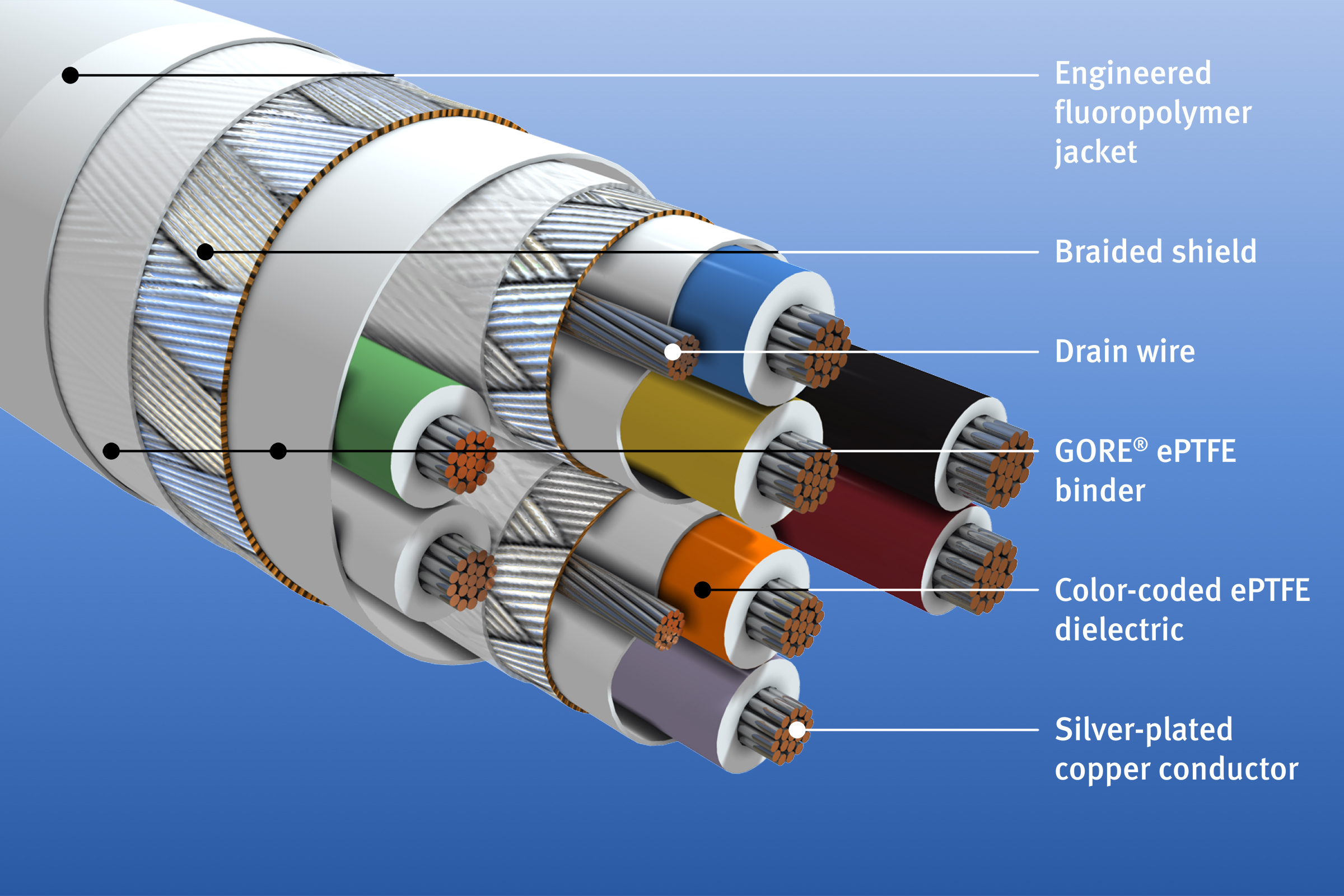
Table 4: Product Specifications
| Part Number | GSC-03-84761-26D |
|---|---|
| AWG Sizea | 26 (19/38) |
| Nominal Outer Diameter mm (in) | 5.8 (0.228) |
| Minimum Bend Radius mm (in) | Static (<20 bends): 15 (0.59) Dynamic: 60 (2.36) |
| Nominal Weight kg/km (lbs/1000 ft) | 57.0 (38.0) |
| Typical Attenuation dB/1 m (dB/3.28 ft) | 1.0 @ 625 MHz 1.4 @ 1250 MHz 2.1 @ 2500 MHz 3.1 @ 5000 MHz 4.1 @ 7500 MHz |
a Additional gauge sizes available upon request.
GORE Aerospace HDMI 2.0 Cables enable a higher resolution up to 4K at 50/60 (2160p), which is four times the clarity of 1080p/60 video resolution allowing passengers to experience IFE in even higher definition (Figure 8). They also deliver excellent signal integrity for high-speed data transmission up to 18 Gigabit per second (Gbps) over longer distances (Table 5). In addition, these lightweight cable bundles have a smaller diameter that increases flexibility with a tighter bend radius making them easier to route in small areas of an aircraft (Figure 9).
Typical Applications
- Electronic flight bag (EFB)
- Flight management systems
- In-flight entertainment (IFE) systems
- Portable electronic devices
- Weather mapping
Figure 8: GORE® Aerospace HDMI 2.0 Cables
Standards Compliance
- ANSI/NEMA WC 27500 Performance Requirements: Environmental Testing, Jacket and Marking
- AS4373 Test Methods for Insulated Electric Wire
- FAR Part 25, Appendix F, Part I, BSS7230, and ABD0031 (AITM 2.0005): Flammability
- FAR Part 25, Appendix F, Part V, BSS7238, and ABD0031 (AITM 3.0008B): Smoke Density
- BSS7239 and ABD0031 (AITM 3.0005): Toxicity
Table 5: Cable Properties
Electrical
| Property | Value |
|---|---|
| Standard Impedance (ohms) | 100 ± 10 |
| Voltage Rating (V) | 150 |
| Capacitance [pF/m (pF/ft)]a | 16 |
a Twisted quad only.
Mechanical and Environmental
| Property | Value |
|---|---|
| Jacket Material | Engineered Fluoropolymer |
| Jacket Color | White |
| Conductor | High-Speed Pairs: Silver-Plated Copper Alloy Quad/Triad: Silver-Plated Copper |
| Conductor Color-Coding | High-Speed Pairs: Blue/White, Red/White, Green/White, Brown/White Quad: White, Orange, Yellow, Purple Triad: Red, Black, Brown |
| Dielectric Material | ePTFE/PTFE |
| Temperature Range (°C) | -65 to 200 |
Ordering Information
GORE Aerospace HDMI 2.0 Cables are available through several global distributors in a variety of standard sizes (Table 6). Visit gore.com/cable-distributors for the list of distributors. Gore also offers custom cables and terminated assemblies. For more information, please contact a Gore representative.
Figure 9: Smaller Diameter
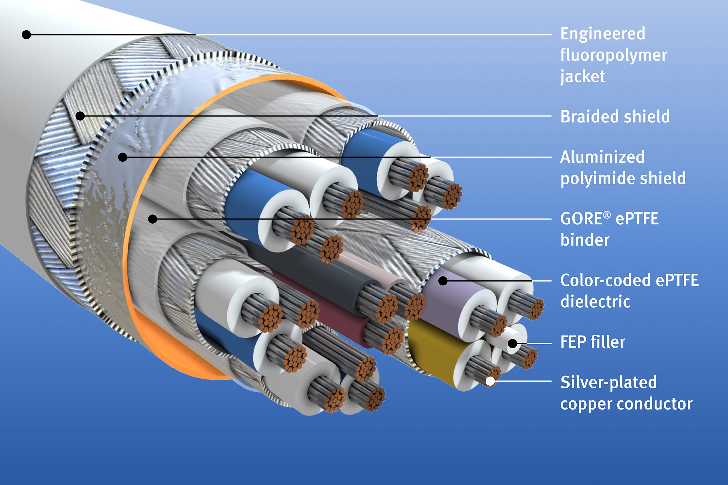
Table 6: Product Specifications
| Part Number | RCN9092 |
|---|---|
| AWG Sizea,b | 26 (19/38) |
| Nominal Outer Diameter mm (in) | 6.9 (0.272) |
| Minimum Bend Radius mm (in) | 13.8 (0.544) |
| Nominal Weight kg/km (lbs/1000 ft) | 57.0 (38.0) |
| Typical Attenuationc dB/5 m (dB/16.4 ft) | 5.0 @ 825 MHz 12.0 @ 2475 MHz 20.0 @ 4125 MHz 25.0 @ 5100 MHz |
a Additional gauge sizes available upon request.
b Size 24 AWG can increase use length up to 7 meters.
c Typical attenuation values are based on maximum recommended use length.
GORE Aerospace Quad Cables provide outstanding electrical and mechanical performance compared to standard quad cables — making them an ideal solution for a variety of high-speed data protocols (Figure 10). For Cat5e requirements, they maintain reliable signal transmission up to 70 meters for size 24 AWG and 50 meters for size 26 AWG (Table 7). In addition, the unique design of these cables offers significant size and weight savings when compared to conventional constructions such as twisted pair or standard quad cables (Figure 11). This size 26 AWG quad design is approximately 40 percent smaller than the common dual twisted pair constructions and has saved as much as 11.5 pounds per aircraft (Figure 12).
Typical Applications
- Box-to-box systems
- Digital visual interface (DVI)
- Ethernet networks
- High-definition serial digital interface (HD-SDI)
Figure 10: GORE Aerospace Quad Cables
Standards Compliance
- ANSI/NEMA WC 27500 Performance Requirements: Environmental Testing, Jacket and Marking
- IEEE 802.3 1000BASE-T Gigabit Ethernet Cables: Ethernet Standard
- AS4373 Test Methods for Insulated Electric Wire
- FAR Part 25, Appendix F, Part I, BSS7230, and ABD0031 (AITM 2.0005): Flammability
- FAR Part 25, Appendix F, Part V, BSS7238, and ABD0031 (AITM 3.0008B): Smoke Density
- BSS7239 and ABD0031 (AITM 3.0005): Toxicity
Table 7: Cable Properties
Electrical
| Property | Value |
|---|---|
| Standard Impedance (ohms) | 100 ± 5 |
| Voltage Rating (V) | < 50 |
| Velocity of Propagation (nominal) (%) | > 70 |
| Near-End Crosstalk (NEXT) dB min @ 10 MHz dB min @ 100 MHz |
50 35 |
| Capacitance [pF/m (pF/ft)] | 50 (15) |
| Test Voltage (DC) Conductor-to-Conductor Conductor-to-Shield |
2500 2500 |
Mechanical and Environmental
| Property | Value |
|---|---|
| Jacket Material | Engineered Fluoropolymer |
| Jacket Color | White |
| Conductor | Silver-Plated Copper Alloy |
| Conductor Color-Coding | Blue, Red, Green, Yellow |
| Dielectric Material | ePTFE/PTFE |
| Temperature Range (°C) | -65 to 200 |
Figure 11: Smaller Quad Cable Design
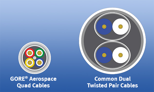
Figure 13: Eye Pattern of a 24 AWG
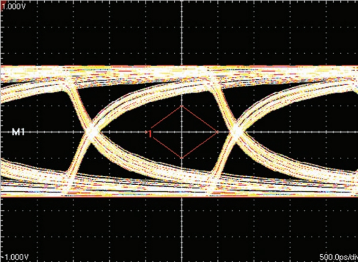
Input Signal: 1.1 Vp-p, 27-1 PSRB Pattern
Signal Integrity with Flexure
To ensure signal integrity with flexure of GORE Aerospace Quad Cables, the eye pattern of a 50-ft cable transmitting 500 Mbps of data was evaluated before and during flexure. The diamond-shaped eye mask indicates the minimum receiver sensitivity. Results showed that GORE® Aerospace Quad Cables passed the test with margin, indicating greater transmission length is possible (Figures 13 and 14).
Figure 12: Lightweight Construction
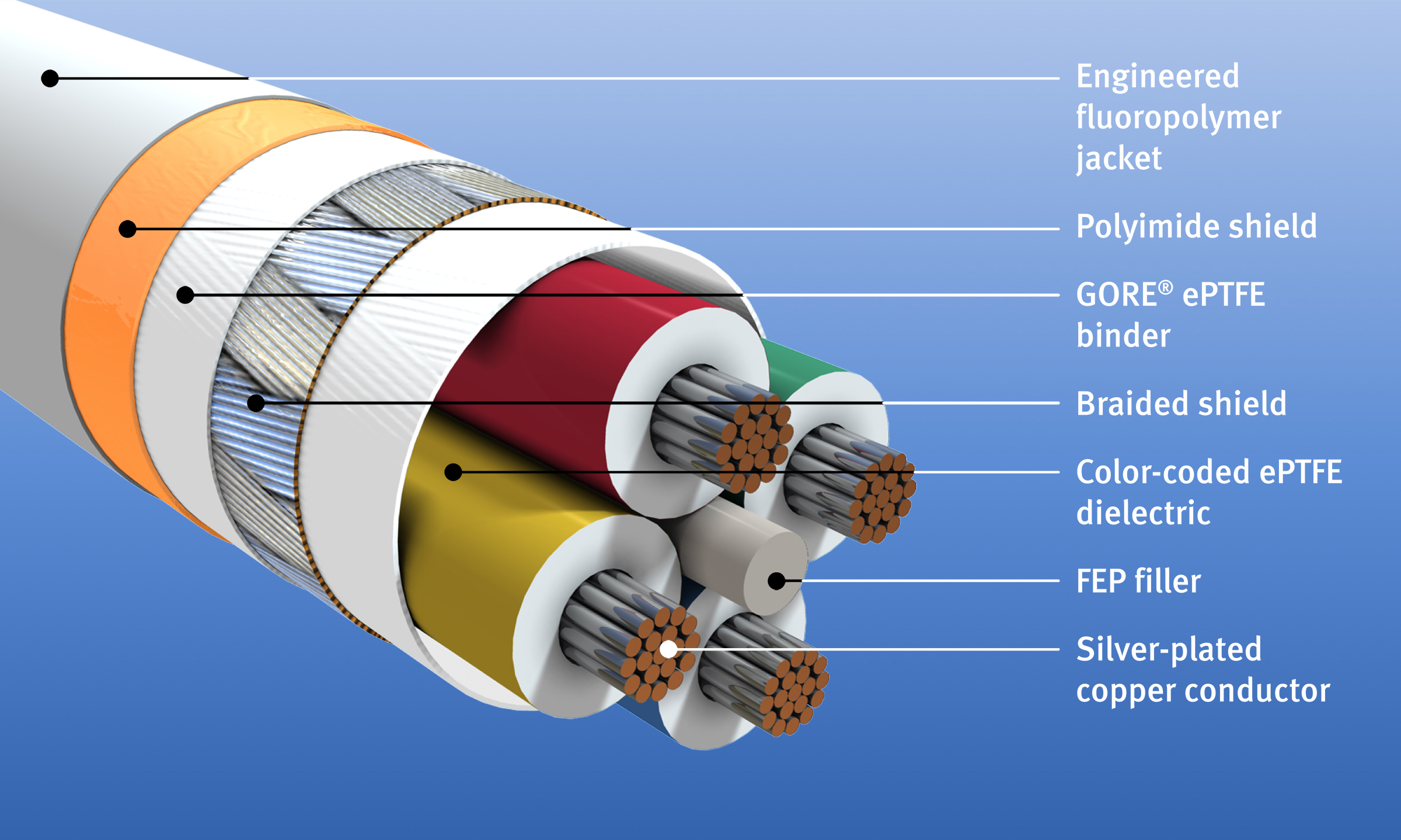
Figure 14: Eye Pattern of a 24 AWG with Flexure
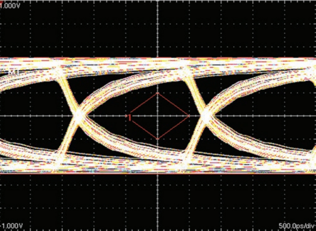
Input Signal: 1.1 Vp-p, 27-1 PSRB Pattern
Ordering Information
GORE® Aerospace Quad Cables are available through several global distributors in a variety of standard sizes (Table 8). Visit gore.com/cable-distributors for the list of distributors. Gore also offers custom cables and terminated assemblies. For more information, please contact a Gore representative.
Table 8: Product Specifications
| Part Number | GSC-03-84608-00 | GSC-03-84820-00 |
|---|---|---|
| AWG Size | 24 (19/36) | 26 (19/38) |
| Nominal Outer Diameter mm (in) | 4.0 (0.157) | 3.2 (0.125) |
| Minimum Bend Radius mm (in) | 20 (0.787) | 15 (0.590) |
| Nominal Weight kg/km (lbs/1000 ft) | 33.0 (22.0) | 23.0 (15.0) |
| Typical Attenuationa 24 AWG: dB/70 m (dB/230 ft) 26 AWG: dB/50 m (dB/164 ft) |
6.5 @ 10 MHz 22.0 @ 100 MHz |
6.5 @ 10 MHz 22.0 @ 100 MHz |
a Typical attenuation values are based on maximum recommended Cat5e use length.
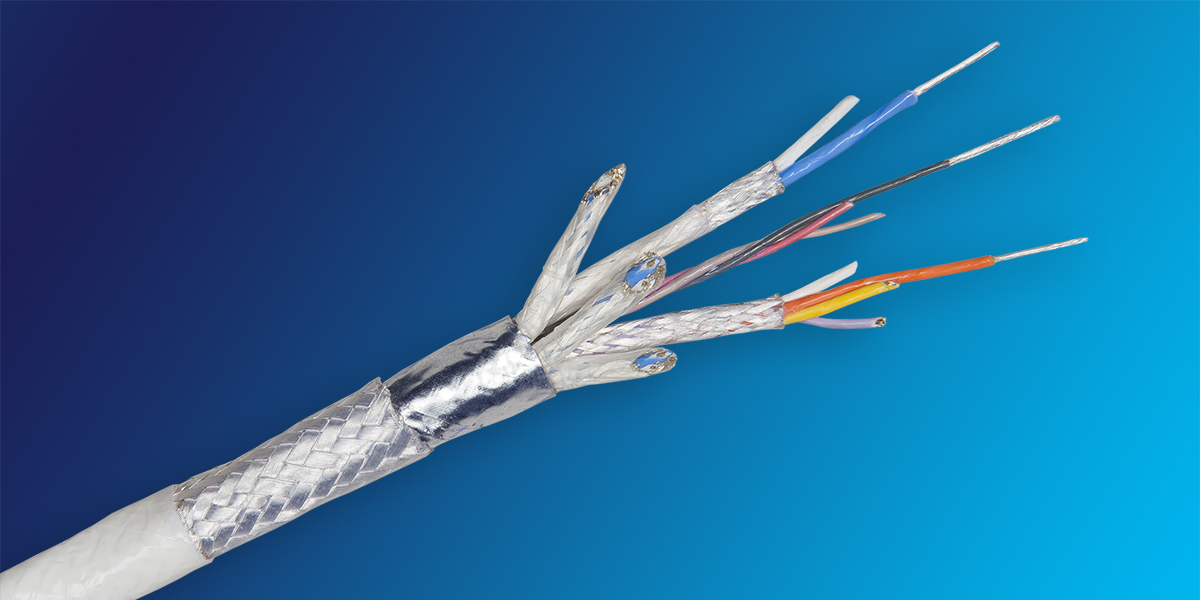
For applications with limited system architecture design, GORE® Aerospace Dual Gigabit Cables can be reliably used as a hybrid between an Ethernet Cat6a cable and two quad cables (Figure 15). They maintain reliable signal transmission for Cat6a requirements up to 10 gigabits for 65 meters. When used as a dual quad cable, they maintain reliable signal transmission at gigabit plus speeds up to 50 meters for each quad cable (Table 9). They are designed to fit most high-speed aerospace connectors, including size 8 contacts for 38999, ARINC and others, as well as Quadrax connectors. In addition, these cables improve installation because they are significantly smaller, lighter weight and highly flexible with a tighter bend radius which makes initial routing easier (Figure 16).
Typical Applications
- Avionics networks
- Cabin management systems
- Digital video systems
- Ethernet backbone
- Flight management systems
- In-flight entertainment (IFE) systems
Figure 15: GORE Aerospace Dual Gigabit Cables
Standards Compliance
- ANSI/NEMA WC 27500 Performance Requirements: Environmental Testing, Jacket and Marking
- IEEE 802.3 1000BASE-T Gigabit Ethernet Cables: Ethernet Standard
- AS4373 Test Methods for Insulated Electric Wire
- FAR Part 25, Appendix F, Part I, BSS7230, and ABD0031 (AITM 2.0005): Flammability
- FAR Part 25, Appendix F, Part V, BSS7238, and ABD0031 (AITM 3.0008B): Smoke Density
- BSS7239 and ABD0031 (AITM 3.0005): Toxicity
Table 9: Cable Properties
Electrical
| Property | Value |
|---|---|
| Standard Impedance (ohms) | 100 ± 10 |
| Voltage Rating (V) | 500 |
| Velocity of Propagation (nominal) (%) | 80 |
| Time Delay (nominal) [ns/m (ns/ft)] 24 AWG | 4.10 (1.25) |
| Capacitance [pF/m (pF/ft)] | 42.6 (13) |
| Dielectric Withstanding Voltage (Vrms) Conductor-to-Conductor Conductor-to-Shield |
1500 1000 |
Mechanical
| Property | Value |
|---|---|
| Jacket Material | Engineered Fluoropolymer |
| Jacket Color | White |
| Conductor | Silver-Plated Copper |
| Conductor Color-Coding | Solid Blue/White with Blue Stripe Solid Orange/White with Orange Stripe Solid Green/White with Green Stripe Solid Brown/White with Brown Stripe |
| Dielectric Material | ePTFE/PTFE |
| Temperature Range (°C) | -65 to 200 |
Ordering Information
GORE Aerospace Dual Gigabit Cables are available through several global distributors in a variety of standard sizes (Table 10). Visit gore.com/cable-distributors for the list of distributors. Gore also offers custom cables and terminated assemblies. For more information, please contact a Gore representative.
Figure 16: Highly Flexible Construction
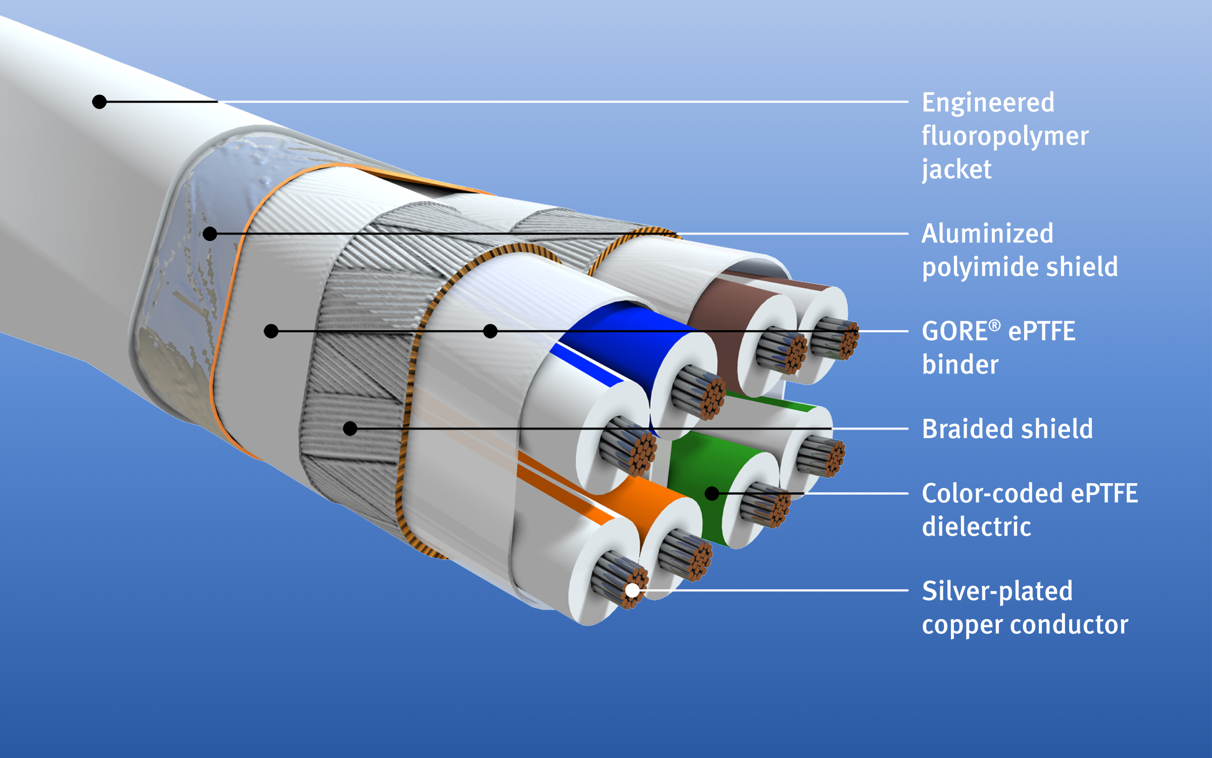
Table 10: Product Specifications
| Part Number | RCN9088-26 |
|---|---|
| AWG Size | 26 (19/38) |
| Nominal Outer Diameter mm (in) | 5.6 (0.22) |
| Minimum Bend Radius mm (in) | 10.2 (0.44) |
| Nominal Weight kg/km (lbs/1000 ft) | 47 (32) |
| Typical Attenuationa dB/65 m (dB/213 ft) | @100 MHz: 19.1 @200 MHz: 27.6 @500 MHz: 45.3 |
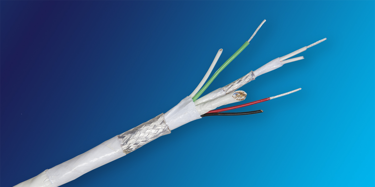
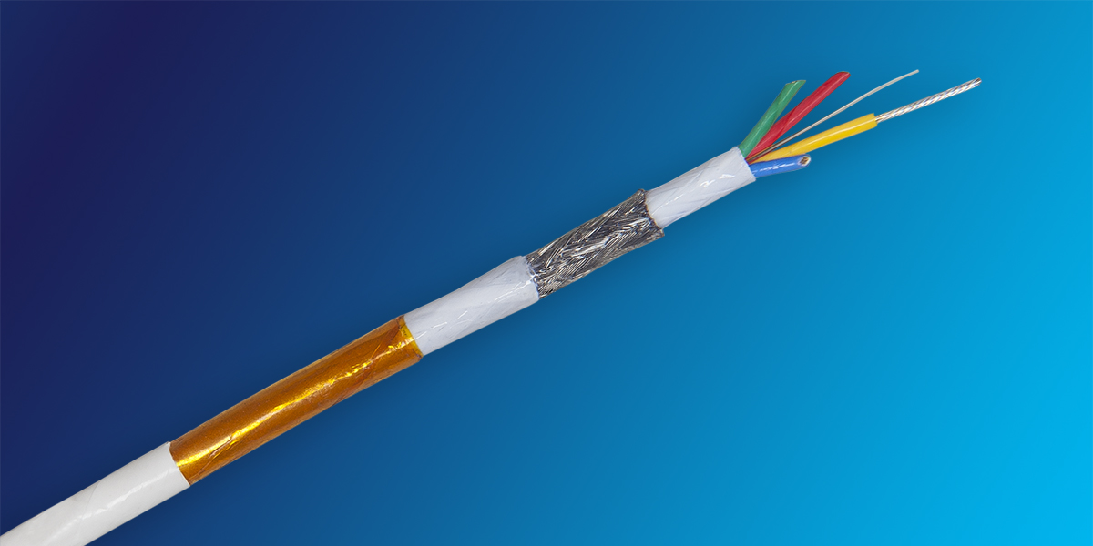
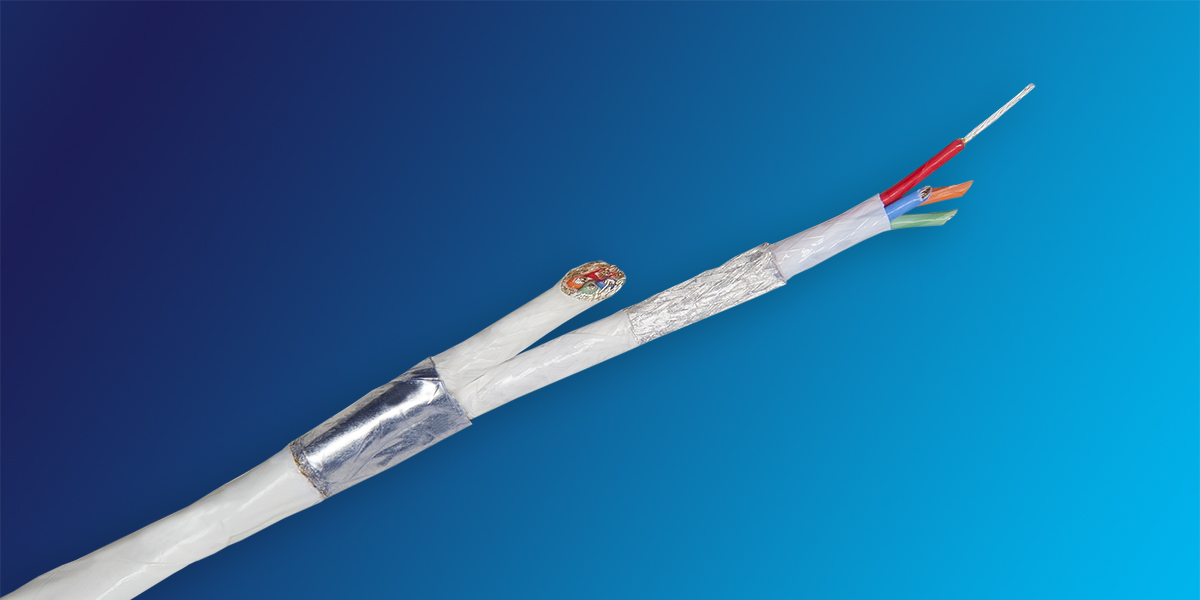
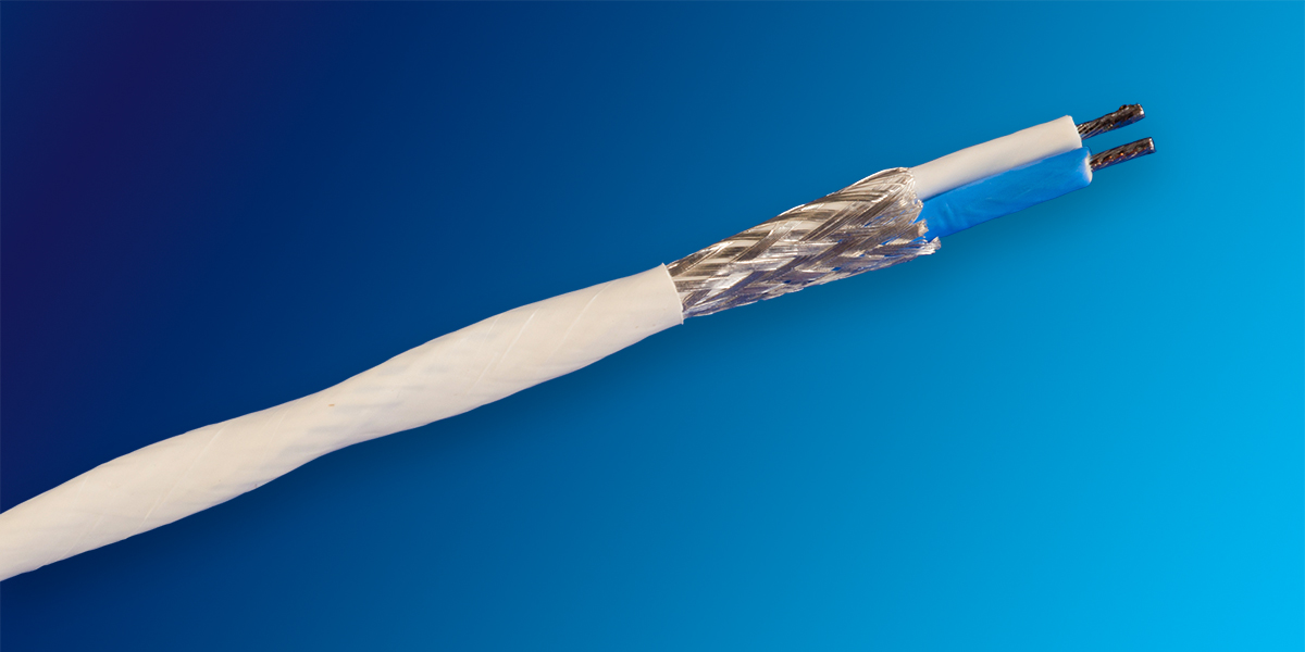
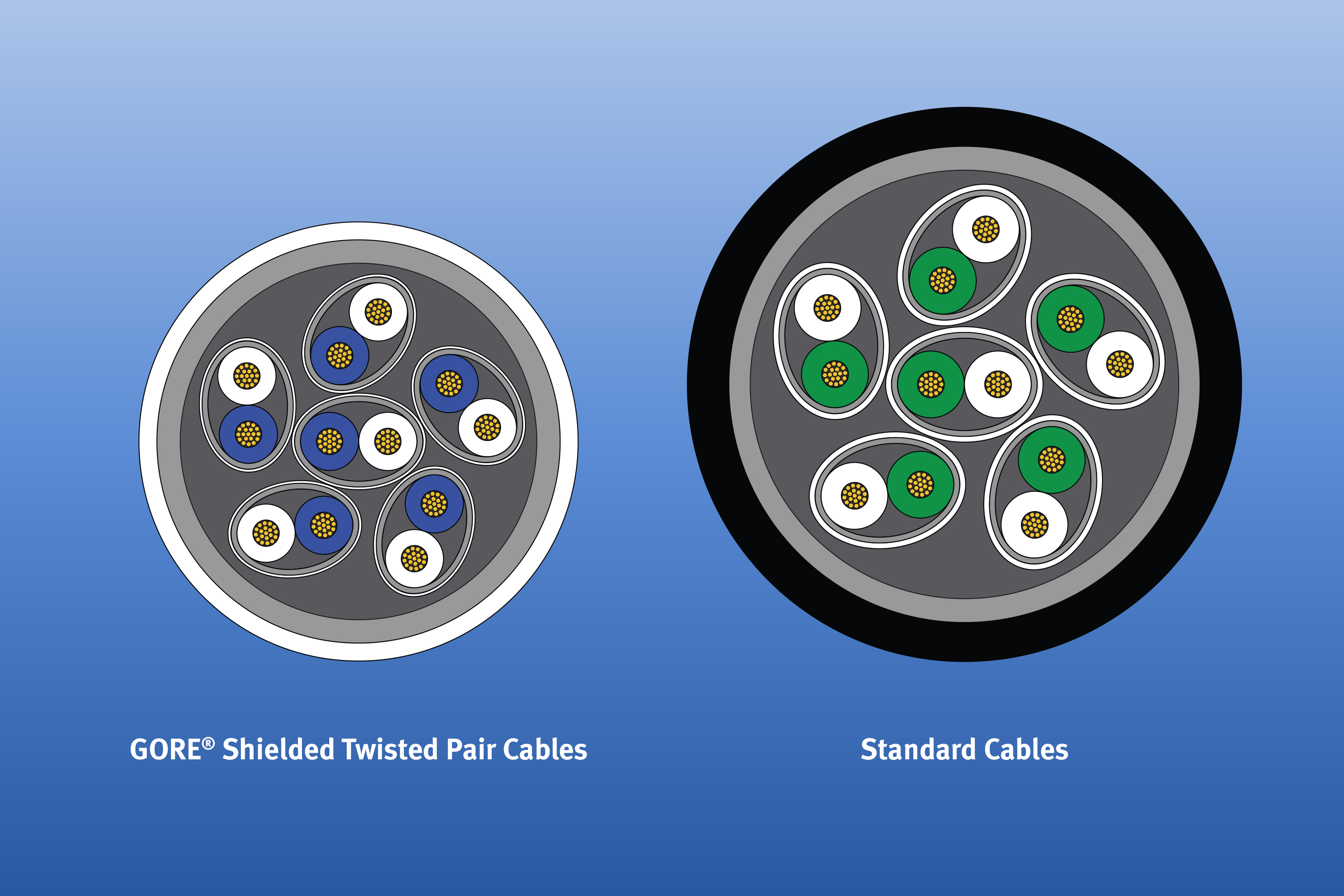
Well-suited for aerospace harness applications, GORE Shielded Twisted Pair Cables are highly flexible and easy to route in confined spaces (Figure 17). These cables provide excellent signal integrity while reducing weight by as much as 35 percent when compared to standard cables (Figures 18 and 19). In addition, the combination of materials in this construction supports a wide temperature range to meet the most demanding aerospace environments (Table 11).
Typical Applications
- Avionics electronics
- Cabin management systems
- Digital video systems
- Ethernet networks
- Serial buses
Figure 17: GORE Shielded Twisted Pair Cables
Standards Compliance
- ANSI/NEMA WC 27500 Performance Requirements: Environmental Testing, Jacket and Marking
- FAR Part 25, Appendix F, Part I, BSS7230, and ABD0031 (AITM 2.0005): Flammability
- FAR Part 25, Appendix F, Part V, BSS7238, and ABD0031 (AITM 3.0008B): Smoke Density
- BSS7239 and ABD0031 (AITM 3.0005): Toxicity
Table 11: Cable Properties
Electrical
| Property | Value |
|---|---|
| Standard Impedance (ohms)s | 100 ± 10 |
| Voltage Rating (V) | 500 |
| Velocity of Propagation (nominal) (%) | 80 |
| Time Delay (nominal) [ns/m (ns/ft)] - 24 AWG | 4.07 (1.24) |
| Capacitance [pF/m (pF/ft)] | 42.6 (13) |
| Dielectric Withstanding Voltage (Vrms) Conductor-to-Conductor Conductor-to-Shield |
1500 1000 |
a Contact Gore for other impedance options.
Mechanical / Environmental
| Property | Value |
|---|---|
| Jacket Material | Engineered Fluoropolymer |
| Jacket Color | White |
| Conductor | Silver-Plated Copper |
| Conductor Color-Coding | White and Blue |
| Dielectric Material | ePTFE/PTFE |
| Dielectric Material | -55 to 200 |
Figure 18: Smaller, Lighter Cable Design
Ordering Information
GORE Shielded Twisted Pair Cables are available through several global distributors in a variety of standard sizes (Table 12). Visit gore.com/cable-distributors for the list of distributors.
Figure 19: Durable Construction
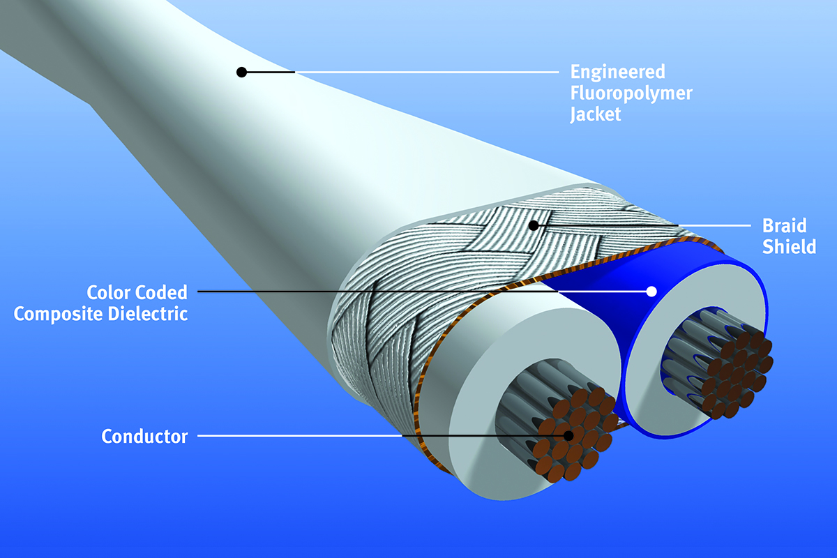
Gore also offers custom cables and terminated assemblies. For more information, please contact a Gore representative.
Table 12: Product Specifications
| Part Number | DXN2600 | DXN2601 | DXN2602 | DXN2603 | DXN2604 | DXN2604 |
|---|---|---|---|---|---|---|
| AWG Size | 20 (19/32) | 22 (19/34) | 24 (19/36) | 26 (19/38) | 28 (19/40) | 30 (19/42) |
| Nominal Outer Diameter Major mm (in) | 5.0 (0.20) | 3.81 (0.15) | 3.23 (0.13) | 2.52 (0.10) | 1.98 (0.08) | 1.78 (0.07) |
| Nominal Outer Diameter Minor mm (in) | 3.68 (0.15) | 2.79 (0.11) | 2.3 (0.09) | 2.1 (0.08) | 1.8 (0.07) | 1.52 (0.06) |
| Minimum Bend Radius mm (in) | 25 (0.98) | 19.1 (0.75) | 16.2 (0.64) | 12.6 (0.49) | 9.9 (0.39) | 8.9 (0.35) |
| Nominal Weight kg/km (lbs/1000 ft) | 31.7 (21.3) | 23.2 (15.6) | 16.8 (11.3) | 12.8 (8.6) | 8.6 (5.8) | 7.1 (4.8) |
| Typical Attenuation dB/30 m (dB/100 ft) | @100 MHZ: 4.8 @200 MHZ: 6.8 @500 MHz: 11.3 @1 GHz: 16.4 |
@100 MHZ: 6.6 @200 MHZ: 9.8 @500 MHz: 15.7 @1 GHz: 23.5 |
@100 MHZ: 7.6 @200 MHZ: 10.7 @500 MHz: 17.3 @1 GHz: 25.0 |
@100 MHZ: 9.4 @200 MHZ: 13.8 @500 MHz: 21.5 @1 GHz: 31.2 |
@100 MHZ: 13.2 @200 MHZ: 19.2 @500 MHz: 32.0 @1 GHz: 46.8 |
@100 MHZ: 20.9 @200 MHZ: 23.6 @500 MHz: 38.3 @1 GHz: 56.9 |
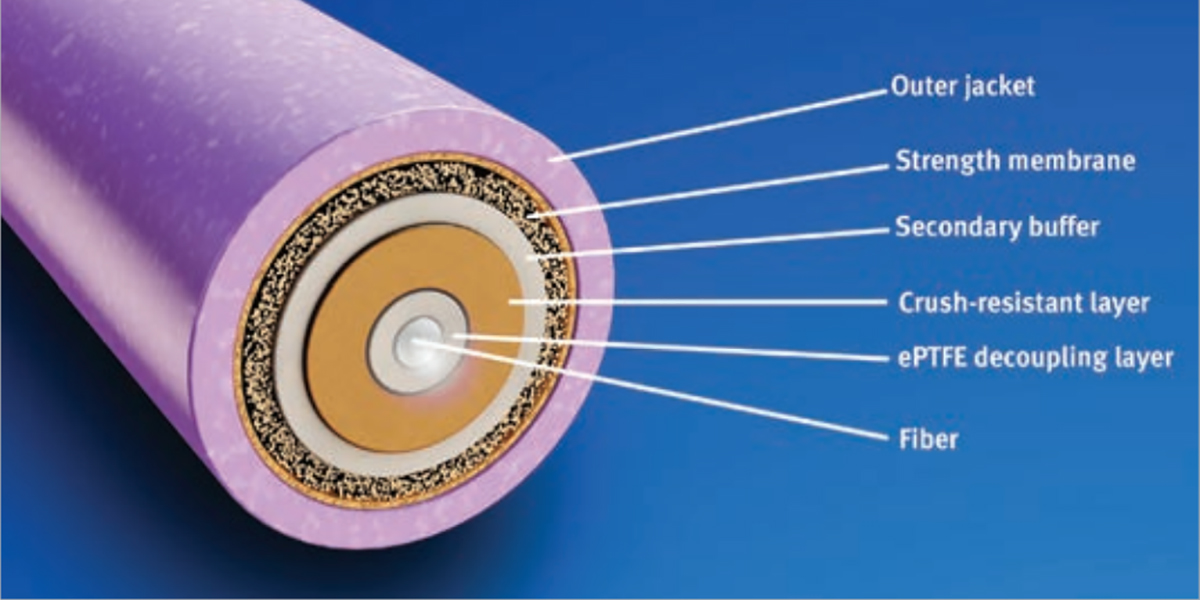
Gore has packaged the standard fiber optic cable in a unique construction that improves all aspects of performance to meet the civil industry’s ever-increasing data needs (Figure 20). GORE® Aerospace Fiber Optic Cables withstand the challenging environments they encounter throughout an aircraft’s service life. These cables deliver excellent signal integrity for high-speed data transmission in wide temperature ranges (Table 13). In addition, The unique dual buffering system in the construction of these cables resists crushing, kinking and abrasion while maintaining reliable signal integrity before and after installation (Figure 21). The combination of materials in this construction also increases fiber movement under compression that improves termination with standard aerospace connectors.
Typical Applications
- Avionics networks
- Cabin management systems
- Digital video systems
- Ethernet backbone
- Flight management systems
- In-flight entertainment (IFE) systems
- Transceivers
- Weather radar systems
Figure 20: GORE Aerospace Fiber Optic Cables
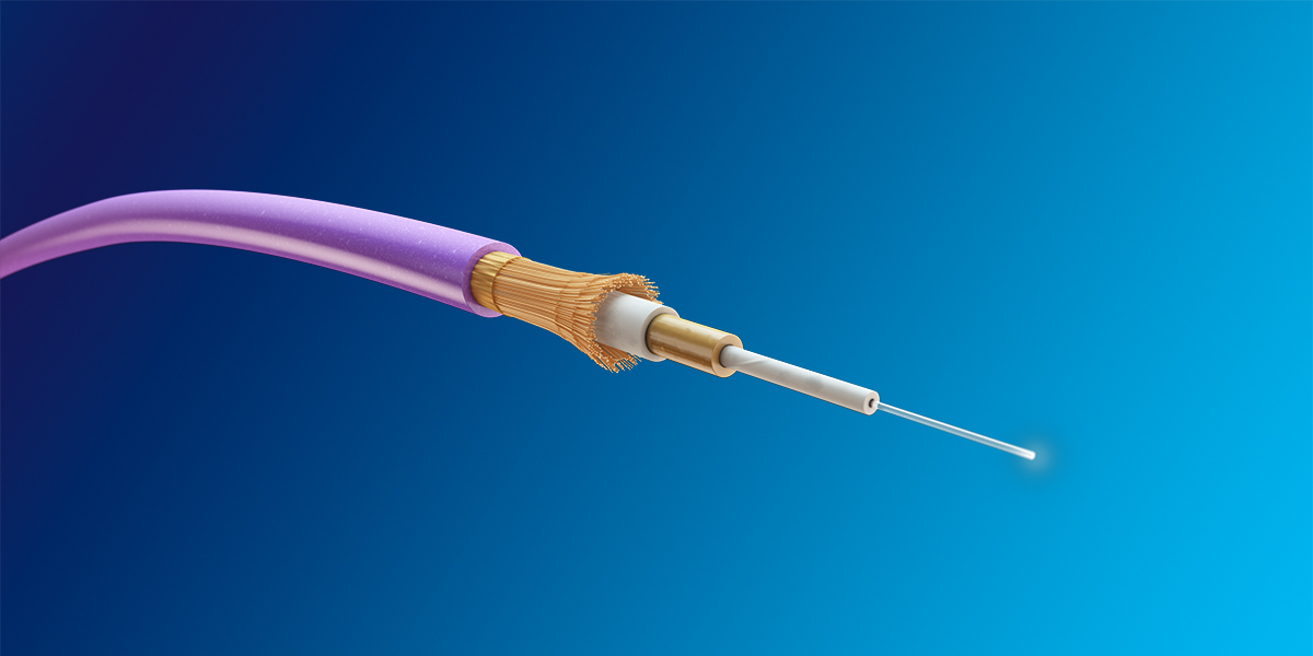
Figure 21: Robust Construction
Standards Compliance
- ANSI/NEMA WC 27500 Performance Requirements: Environmental Testing, Jacket and Marking
- EN4641-301
- ARINC 802 Performance and Environmental Requirements
- FAR Part 25, Appendix F, Part I, BSS7230, and ABD0031 (AITM 2.0005): Flammability
- FAR Part 25, Appendix F, Part V, BSS7238, and ABD0031 (AITM 3.0008B): Smoke Density
- BSS7239 and ABD0031 (AITM 3.0005): Toxicity
Table 13: Cable Properties
Electrical
| Property | Value |
|---|---|
| Maximum Optical Loss at 850 nm (dB/km) | 4.0 |
| Maximum Optical Loss at 1310 nm (dB/km) | 3.0 |
Mechanical / Environmental
| Property | Value |
|---|---|
| Jacket Material | Engineered Fluoropolymer |
| Core Type | Multi-mode |
| Coating Type | High-temperature Acrylate |
| Dielectric Material | ePTFE/PTFE |
| Temperature Range (°C) | -60 to 135 |
Added Durability
Gore evaluated the durability of its cable compared to a leading alternative cable using the EN-4641-301 test method. Results showed that GORE® Aerospace Fiber Optic Cables provided reliable mechanical performance with greater crush resistance for extended service life (Figures 22 and 23). The enhanced durability of these cables allows for lower force to move the fiber under compression while still maintaining excellent signal transmission. With an exceptional balance of properties, GORE® Aerospace Fiber Optic Cables deliver improved reliability and extended service life in a more robust construction without sacrificing size or weight.
Ordering Information
GORE Aerospace Fiber Optic Cables are available through several global distributors in a variety of standard sizes (Table 14). Visit gore.com/cable-distributors for the list of distributors. Gore also offers custom cables and terminated assemblies. For more information, please contact a Gore representative.
Figure 22: Greater Crush Resistance at 850 nm
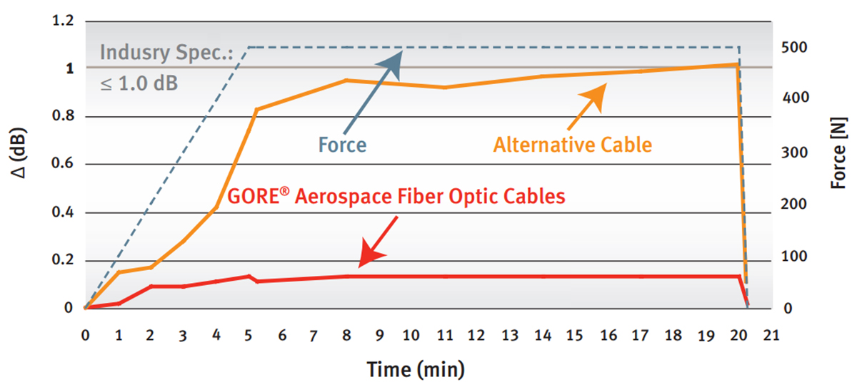
Figure 23: Greater Crush Resistance at 1300 nm
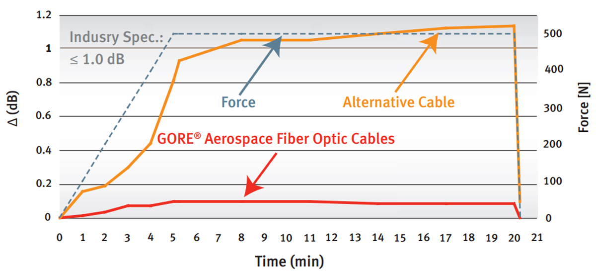
Table 14: Product Specifications
| Part Number | GSC-13-84639-04 | GSC-13-84639-07 | GSC-13-84640-04 | GSC-13-84640-07 |
|---|---|---|---|---|
| Core/ Cladding/ Coating | 50/125/245 | 50/125/245 | 62.5/125/245 | 62.5/125/245 |
| Jacket Color | Yellow | Purple | Yellow | Purple |
| Nominal Outer Diameter mm (in) |
1.8 (0.07) | 1.8 (0.07) | 1.8 (0.07) | 1.8 (0.07) |
| Minimum Bend Radius mm (in) |
18.0 (0.71) | 18.0 (0.71) | 18.0 (0.71) | 18.0 (0.71) |
| Nominal Weight (g/m) |
4.0 | 4.0 | 4.0 | 4.0 |
| Tensile Strength (N max) |
200 | 200 | 200 | 200 |
a Contact a Gore representative for a bend-insensitive fiber option or specific fiber glass type.
NOTICE — USE RESTRICTIONS APPLY Not for use in food, drug, cosmetic or medical device manufacturing, processing, or packaging operations.
GORE and designs are trademarks of W. L. Gore & Associates ©2016 W. L. Gore & Associates, Inc. ACS-0211-DAT-US-R2-JUN16