ASTM F36: Standard Test Method for Compressibility and Recovery of Gasket Materials
This test method covers determination of the short-time compressibility and recovery at room temperature of sheet-gasket materials. It is not intended as a test for compressibility under prolonged stress application, generally referred to as "creep."
Source: ASTM International. Standard Test Method for Compressibility and Recovery of Gasket Materials - Designation: F36–99 (Reapproved 2009)
| Thickness | Compressibility (average of 3 tests) |
Recovery (average of 3 tests) |
|
|---|---|---|---|
ASTM F36 Procedure L
|
1.5 mm (1/16") |
56% | 8% |
ASTM F38: Standard Test Methods for Creep Relaxation of a Gasket Material
ASTM F38 provides a means of measuring the amount of creep relaxation of a gasket material at a predetermined time after a compressive stress has been applied. This test method is designed to compare related materials under controlled conditions and their ability to maintain a given compressive stress as a function of time.
Source: ASTM International. Standard Test Methods for Creep Relaxation of a Gasket Material - Designation: ASTM F38 - 00(2014)
| Thickness | Relaxation (average of 3 tests) |
|
|---|---|---|
ASTM F38-95 Method B
|
0.8 mm (0.030") | 23% |
ASTM F37: Standard Test Methods for Sealability of Gasket Materials
ASTM F37 provides a means of evaluating the sealing properties of sheet and solid form-in-place gasket materials at room temperature. This test method is designed to compare gasket materials under controlled conditions and to provide a precise measure of leakage rate.
Source: ASTM International. Standard Test Methods for Sealability of Gasket Materials - Designation: ASTM F37 - 06(2013)
| Thickness | Leak rate | |
|---|---|---|
ASTM F37-00 Method B
|
1.5 mm (1/16") | 0.3 ml/h |
Test Method Overview
This test method is currently being proposed as a new ASTM test method by the Committee F03 on Gaskets. ARLA determines the long term (aged) relaxation, leakage, weight loss and adhesion performance of gasket materials for pressurised bolted flanged connections. A mechanical integrity check of the material is also done. The method applies mainly to circular gasket products typically used in process or power plant pressure vessels and piping.
Source: ASTM International. New Test Method for AGED RELAXATION LEAKAGE ADHESION PERFORMANCE of Gaskets - Designation: ASTM WK26065
General Test Method

- Place the gasket in the ARLA fixture
- Measure the distance between platens
- Load the gasket to initial compressive stress
- Measure the stud length
- Measure the distance between platens
- Measure the leak rate (using a Helium Mass Spectrometer) using helium gas at 800 psig
- Age by placing the loaded fixture in a non-circulating air oven
- Remove the fixture from the oven and cool to room temperature
- Measure the stud length
- Measure the distance between platens
Test Results
| Gasket Thickness | % Relaxation (Average of 3 Tests) | Helium Leak Rate before aging (mg/s) | Helium Leak Rate after aging (mg/s) | |
|---|---|---|---|---|
| ARLA 5000 psi compressive stress
|
1/16" | 30.77 | 1.04E-04 | 1.42E-05 |
| 1/8" | 43.19 | 1.04E-03 | <1.0E-7 |
Test Method Overview
"The aim of the VDI guideline is to analyze and organize the applicable seal connection conditions based on the technical standard. Furthermore to complete the conditions, including latest research results, and advise the user in selection, interpretation, design, and assembling of flange joints in particular consideration of the gaskets."(1) "The here described blowout safety test of seals in sealing systems with even flanges corresponds with the current state of test engineering [...] a seal itself cannot accomplish blowout safety. It always depends on the entire system of the flange joint.
General Test Procedure
- Installation of seal with installation surface pressure in four steps (25 %, 50 %, 75 % and 100 % of bolt force through crosswise tightening). Installation surface pressure and seal thickness are to be indicated in the test record. The lift-off force, caused by the nominal pressure, referring to the middle seal diameter, shall additionally be considered in all testing steps.
- Retightening to installation surface pressure after 5 minutes.
- Flange heating to temperature with 2 K/min in recirculation furnace or using inside heated cartridges.
- Maintenance of thermal storage temperature for minimum 48 hours.
- Cooling down of the flange to ambient temperature.
- Measurement of the remaining surface pressure.
Test Step 1
The blowout safety test is performed with nitrogen up to the 1.5-fold of the nominal pressure. Tests with higher pressures are allowed, if required. The internal pressure is to be increased stepwise, in steps of 5 bar to the above mentioned pressure. The holding period per pressure stage amounts to a minimum of 2 min.
As "blowout" is defined, if, within 5 s, a pressure decay of Δp ≥ 1 bar· (V0 = test room volume) is exceeded. The achieved internal pressure is to be indicated in the test record. If blowout did not occur until the maximum test pressure, the test is to be continued according to test step 2.
Test Step 2
The internal pressure is discharged and the surface pressure is reduced to 5 N/mm2 with regard to lifting force caused by the internal pressure. Variations of the surface pressure are to be stated in the testing report."(2)
(1) Source: Verein Deutscher Ingenieure e. V.: VDI2200: Tight flange connections - Selection, calculation, design and assembly of bolted flange connections, June 2007, page 4
(2) Source: ibidem, page 64
Test Results
| Thickness | Exposure Temperature | Initial Gasket Stress | Test Step 1 | Test Step 2 | |
|---|---|---|---|---|---|
| VDI 2200 (06-2007) DN40 / PN40 Steel |
3.2 mm (1/8") |
230°C (446°F) |
30MPa (4351psi) |
Yes, 60 bar (870 psi) |
Yes, 60 bar (870 psi) |
Test Method Description
This test method is currently being proposed as a new ASTM test method by the Committee F03 on Gaskets. This test method provides a means to determine realistic temperature limits for polytetrafluoroethylene (PTFE) based sheet or sheet-like gaskets to assist in avoiding catastrophic failure or blowout. This test method focuses on flanged joints common in the chemical process industry for moderate temperature ASME B16.5 Class 150 and Class 300 services.
Source: ASTM International. New Test Method for Hot Blowout and Thermal Cycling Performance for Polytetrafluoroethylene (PTFE) Sheet or Sheet-Like Gaskets - Designation: ASTM WK26064
General Test Procedure (Draft 7)
- A gasket is loaded in a Hot Blow Out Test Rig, which is comprised of NPS 3 Class 150 or Class 300 raised face flanges. Using a torque wrench and best installation practices, the specified compressive stress is applied to the gasket.
- A waiting period for gasket creep and relaxation of 30 minutes is observed before the gasket is reloaded to the specified gasket stress.
- Another 30 minutes waiting period is observed before the rig is pressurized with helium gas.
- For HOBT without thermal cycles, once the pressure is applied, the temperature is increased up to 648.9°C (1200°F) maximum at a 16.1°C (3°F) per minute rate until blow-out or maximum temperature of the rig is reached.
- For HOBT with thermal cycles, once the pressure is applied, the temperature is increased at 16.1°C (3°F) per minute rate. The fixture is then cooled to room temperature. This cycle is repeated two more times for a total of three thermal cycles per test.
The procedure consists of three tests:
Test 1: HOBT without thermal cycles.
Test 2: HOBT with 3 thermal cycles using temperature estimation from Test 1.
Test 3: HOBT with 3 thermal cycles using temperature estimation from Test 2.
Test Results
| Gasket Thickness | Blowout Temperature | Blowout Stress | Blowout Pressure | Trial Gasket Temperature Tgs | |
|---|---|---|---|---|---|
HOBT with Cycling Draft 7
|
3.2mm (1/8") |
392.2°C (738°F) |
8.8MPa (1271 psi) |
30bar (435 psig) |
Actual: 339°C (635°F) Limited to: 315°C (600°F) |
Test Method Overview
This test method is currently being proposed as a new recommended practice for Gasket Constants for Bolted Joint Design by the Committee F03 on Gaskets. This practice determines room temperature gasket tightness design constants for pressurized bolted flanged connections such as those designed in accordance with The ASME Boiler & Pressure Vessel Code. It applies mainly to all types of circular gasket products and facings typically used in process or power plant pressure vessels, heat exchangers and piping including solid metal, jacketed, spiral wound and sheet type gaskets. As an option, the maximum assembly stress for those gaskets is also determined by this procedure.
Source: ASTM International. New Recommended Practice for GASKET CONSTANTS FOR BOLTED JOINT DESIGN - Designation: ASTM WK10193
Definitions of Test Parameters
| Gb | The gasket stress at Tp = 1 when loading the gasket. It indicates the initial gasket stress required to seat the gasket with tightness. |
|---|---|
| "a" | The slope obtained by linear regression. It indicates the capacity of the gasket to ensure tightness. |
| Gs | The gasket stress at Tp = 1 when unloading the gasket. It indicates the capacity of the gasket to maintain tightness when pressure is applied, as well as the gasket's sensitivity to unloading. |
| Tp | The Tightness Parameter is dimensionless. A value of 1 corresponds to a Helium leak rate of 1 mg/s under atmospheric pressure for a gasket with an outside diameter of 150 mm. Note: the greater the Tp, the greater the gasket tightness. |
| Tpmax | The maximum tightness obtained when loading the gasket. |
| Tpmin | The minimum tightness obtained when unloading the gasket. |
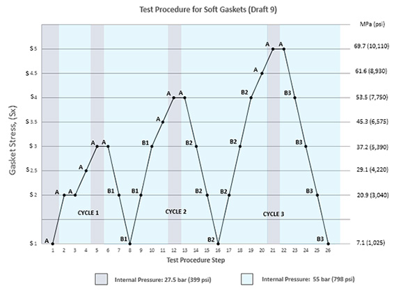
General Test Procedure for Soft Gaskets (Draft 9)
- A gasket is placed in a hydraulic flat platen test rig.
- A series of 3 loadings and unloading cycles is applied during which leak rate is measured at each stress level. Depending on the step, the system is pressurized to either 27.5 bar (399 psi) or 55 bar (798 psi) using helium gas. The holding time at each step is dependent on when a leak rate stabilizes, with a minimum hold time of 1 minute and a maximum hold time of 5 hours.
- The data collected is grouped into two Parts, Part A and Part B, and analyzed to generate the test parameters. Part A represents the initial seating performance of a gasket during initial flange tightening. Data from Part A is used to determine Gb, "a", and Tpmax. Part B simulates actual operating conditions. Data from Part B is used to determine Gs and Tpmin.
ROTT Test Procedure for Soft Gaskets
General Test Procedure for CRUSH (Draft 9)
- The gasket stress is restored to S1 level.
- Loading cycles, with gradually increasing compression stresses, are applied on the gasket during which leak rate is measured at each stress level. The system is pressurized to 27.5 bar (399 psi) using helium gas. The holding time shall not exceed 15 minutes at each stress level.
- The test is complete when the leak rate at a stress level exceeds the leak rate observed at S1 level or when the maximum load of the equipment is reached.
- Maximum Allowable Stress is the maximum stress level where S1 leak rates were maintained.
Test Results
ROTT Draft 9 SOFT Gasket Test Procedure
| Gasket Thickness: 1/16" | Gasket Thickness: 1/8" | |
|---|---|---|
| Gb (psi) | 685 | 770 |
| a | 0.271 | 0.274 |
| Gs (psi) | 6.19E-02 | 9.38E-07 |
| Tpmin | 1416 | 1962 |
| Tpmax | 27706 | 16424 |
| S100 (psi) | 2391 | 2716 |
| S1000 (psi) | 4466 | 5099 |
| S10000 (psi) | 8343 | 9573 |
| Maximum Allowable Gasket Stress (psi) | Greater than 40031 (Equipment Max) | Greater than 40031 (Equipment Max) |