EN 13555 provides the test method for generating the gasket parameters used in EN 1591-1 calculations. With the approval of EN 13555:2014, the informative Annex G now provides some guidance for generating gasket design parameters for form-in-place products. Test results per the 2014 revision will be available soon.
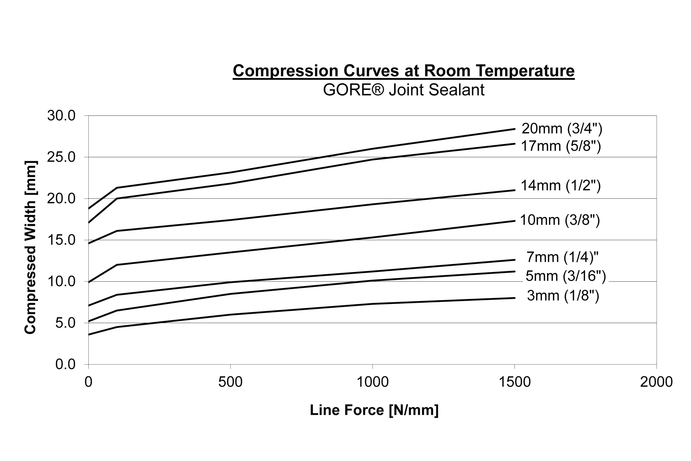
Due to the material properties of monoaxially expanded PTFE, the increase in the gasket width of GORE® Joint Sealant DF depends on the pressure exerted on it. For the configuration and calculation of flange connections it is therefore easier to use line forces instead of gasket stress. The line force, Q*, is the ratio of the force per unit length.
Gasket Constant Definitions
| PQR | A measure of creep relaxation at a predefined temperature. It is the ratio between the gasket stress after relaxation and the initial gasket stress. The ideal PQR value is 1. The closer the test value is to the ideal value, the lower the loss of gasket stress of the seal. |
|---|---|
| Q*min(L) | The minimum required line force at ambient temperature for a certain leakage class L when the seal is first installed. |
| Q*Smin(L) | The minimum required line force for a certain leakage class L in service. |
| Q*Smax | The maximum line force that may be applied on the gasket, without damage or intrusion into the bore, at the indicated temperatures. It depends on the temperature and the seal thickness. |
| E*G | This describes the recovery (elastic behavior) of a seal at load reduction. It is related to the modulus of elasticity. It depends on the applied line force, the seal thickness and the temperature. |
General Test Method Description
| PQR | Creep Relaxation is measured at different temperatures, initial gasket stress, seal thickness values and flange stiffness values. The seal initially is exposed to the predefined gasket stress, then the temperature is increased and maintained for four hours. The residual gasket stress is then measured. |
|---|---|
| Q*min; Q*Smin |
A load is applied to and removed from the seal in predefined increments, with the leakage being measured constantly. The internal pressure is usually 40 bar (test gas: helium). |
| Q*Smax; E*G |
The gasket stress is increased cyclically and then reduced to 1/3 of the previous gasket stress. The seal thickness is then measured. The test is repeated at various temperatures. The E*G value is calculated from the load reductions and thickness changes. For Q*Smax, a sudden drop in seal thickness indicates failure. If a sudden drop occurs, the value of the loading step before failure is taken. In case no failure occurs, the maximum possible gasket stress of the test equipment is taken. The identified value is then used as the initial stress in a PQR test to verify the final Q*Smax under constant loading. |
Test Results
EN 13555 specifies a test flange that is DN40/PN40 in size; therefore, GORE® Joint Sealant DF05 was tested using a stiffness of 500 kN/mm. Results for all other sizes were extrapolated from DF05 results using the following compression curve.
PQR
| Initial Line Force (N/mm) |
Thickness (mm) |
Temperature (°C) |
PQR | |
|---|---|---|---|---|
| 5mm (3/16") | 144(1) | 2 | 20 | 0.73 |
| 144(1) | 2 | 150 | 0.22 |
(1) corresponds to 30MPa initial surface pressure (initial width = 5mm)
Q*min (N/mm)
| L1.0 | L0.1 | L0.01 | L0.001 | |
|---|---|---|---|---|
| 3mm (1/8") | 32 | 89 | 145 | 201 |
| 5mm (3/16") | 50 | 141 | 228 | 317 |
| 7mm (1/4") | 67 | 184 | 292 | 397 |
| 10mm (3/8") | 95 | 258 | 408 | 556 |
| 14mm (1/2") | 128 | 348 | 552 | 754 |
| 17mm (5/8") | 160 | 446 | 721 | 1007 |
| 20mm (3/4") | 165 | 460 | 747 | 1053 |
Q*Smin (N/mm)
| Q*A (N/mm) | QA (MPa) | L1.0 | L0.1 | L0.01 | L0.001 | |
|---|---|---|---|---|---|---|
| 3mm (1/8") | 96 | 32 | 32 | 32 | x | x |
| 192 | 64 | 32 | 32 | x | x | |
| 288 | 96 | 32 | 32 | 49 | x | |
| 384 | 128 | 32 | 32 | 40 | 202 | |
| 5mm (3/16") | 96 | 20 | 48 | 48 | x | x |
| 192 | 40 | 48 | 48 | x | x | |
| 288 | 60 | 48 | 48 | 73 | x | |
| 384 | 80 | 48 | 48 | 61 | 110 | |
| 7mm (1/4") | 96 | 14 | 67 | 67 | x | x |
| 192 | 27 | 67 | 67 | x | x | |
| 288 | 41 | 67 | 67 | 102 | x | |
| 384 | 55 | 67 | 67 | 84 | 146 | |
| 10mm (3/8") | 96 | 10 | 95 | 95 | x | x |
| 192 | 19 | 95 | 95 | x | x | |
| 288 | 29 | 95 | 95 | 144 | x | |
| 384 | 38 | 95 | 95 | 119 | 207 | |
| 14mm (1/2") | 96 | 7 | 127 | 127 | x | x |
| 192 | 14 | 127 | 127 | x | x | |
| 288 | 21 | 127 | 127 | 193 | x | |
| 384 | 27 | 127 | 127 | 160 | 279 | |
| 17mm (5/8") | 96 | 6 | 160 | 160 | x | x |
| 192 | 11 | 160 | 160 | x | x | |
| 288 | 17 | 160 | 160 | 245 | x | |
| 384 | 23 | 160 | 160 | 202 | 354 | |
| 20mm (3/4") | 96 | 5 | 165 | 165 | x | x |
| 192 | 10 | 165 | 165 | x | x | |
| 288 | 14 | 165 | 165 | 252 | x | |
| 384 | 19 | 165 | 165 | 208 | 366 |
Q*smax (N/mm)
| Thickness (mm) |
Temperature (°C) |
Q*smax (N/mm) |
Qsmax (MPa) |
|
|---|---|---|---|---|
| 5mm (3/16") | 2 | 20 | 2000 | 100 |
| 2 | 150 | 2000 | 100 |
E*G
| Thickness (mm) | Temperature (°C) | EG96N/mm (MPa) | EG144N/mm (MPa) | EG192N/mm (MPa) | EG240N/mm (MPa) | EG288N/mm (MPa) | |
|---|---|---|---|---|---|---|---|
| 5mm (3/16") | 2 | 20 | 302 | 417 | 690 | 1059 | 880 |
| 2 | 150 | 254 | 543 | 554 | 989 | 872 |
m & y are gasket constants used for flange design as specified in the ASME Boiler and Pressure Vessel Research Code Division 1 Section VIII Appendix 2. Leak Rates versus Y stresses and m factor for Gaskets is currently being proposed as a new test method in the ASTM F03 Working Group.
Gasket Constant Definitions
m, maintenance factor, is a factor that describes the amount of additional preload required to maintain the compressive load on a gasket after internal pressure is applied to a joint.
y, seating stress, is the minimum compressive stress (psi) required to achieve an initial seal.
| Value | |
|---|---|
| m | 1.5 |
| y | 2500 |
There are no specific test standards for AD 2000 B 7 Gasket Parameters. However, an estimation is provided below. The 2015 edition of "AD 2000-Merkblatt B 7" refers to EN 13555 as a test standard(1) and uses table 9 from VDI 2200(2) for the conversion method. Please note that VDI 2200 states that such a conversion is invalid due to the different measurement methods. "Only the method according to DIN EN 1591-1 and AD 2000 in conjunction with DIN EN 1591-1 and FE analysis can be used for providing stability, leak tightness and TA Luft proof." (3)
Gore supports the use of the AD 2000-Merkblatt B 7 and provides the necessary gasket parameters below.
There are the following relations(1):
k0KD ≙ Qmin · bD
k1 ≙ (QSmin / p) · bD since m ≙ QSmin / p (4)
k0KDϑ ≙ Qsmax · bD
where,
| Qmin | minimum required gasket stress at ambient temperature when the seal is first installed (based on EN13555) |
|---|---|
| QSmin | minimum required gasket stress in service (based on EN13555) |
| QSmax | maximum gasket stress that may be applied on the gasket at an indicated temperature ϑ (based on EN 13555) |
| bD | width of the gasket |
| p | internal pressure of the media |
| k1 | AD 2000 B7 gasket parameter for service condition |
| k0KD | AD 2000 B7 gasket parameter for gasket deformation |
| k0KDϑ | AD 2000 B7 gasket parameter for gasket deformation in service at temperature ϑ |
For GORE® Joint Sealant in 2 mm thickness and with an internal pressure of 10 bar
- k1 = 10 • bD
- k0KD = 18 MPa • bD
- k0KDϑ= 200 MPa • bD temperature ϑ = 150°C (302°F)
If necessary for a specific application, Gore recommends to do individual conversions based on data from EN 13555.
The use of the general values given in table 1 of AD 2000-Merkblatt B 7(5) is not broadly recommended. However they may be applicable depending on the given situation.
Please also note that the quoted standards of DIN 2690 to DIN 2692 were superseded by EN 1514-1 in 1997.
(1) Arbeitsgemeinschaft Druckbehälter: AD 2000-Merkblatt B 7, Berechnung von Druckbehältern, Schrauben, Seite 4, 7.1.2.4, April 2015
(2) Verein Deutscher Ingenieure e. V.: VDI 2200, Tight flange connections - Selection, calculation, design and assembly of bolted flange connections, page 36, table 9, June 2007
(3) Verein Deutscher Ingenieure e. V.: VDI 2290, Emission Control - Sealing constants for flange connections, page 8, June 2012
(4) Please note that factor m = QSmin / p was defined by DIN V 2505 which was superseded by EN 1591-1 where m is no longer used
(5) Arbeitsgemeinschaft Druckbehälter: AD 2000-Merkblatt B 7, Berechnung von Druckbehältern, Schrauben, Seite 6, Tabelle 1, April 2015